Hardware Reference
All RoArm models (M2-S, M2-Pro, M3-S, M3-Pro) are built around the “General Driver for Robots” board — a custom ESP32-based controller designed by Waveshare for serial bus servo control, WiFi communication, and peripheral expansion. The M3 variant of the board adds an INA219 voltage/current monitor, AK09918C compass, QMI8658 6-axis IMU, and a TF card slot.
Driver Board Overview
Section titled “Driver Board Overview”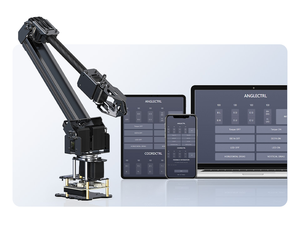 Image: Waveshare
Key Components
Section titled “Key Components”| Component | Description |
|---|---|
| ESP32-WROOM-32 | Main MCU — dual-core 240MHz, WiFi + Bluetooth |
| CP2102 / CH340 | USB-to-serial converter for programming and communication |
| 9-DOF IMU | Onboard inertial measurement unit |
| 0.91” OLED | Status display |
| Serial Bus Interface | Half-duplex UART for servo communication |
| 12V Input | Barrel jack power input for servo and motor drive |
| 5V Regulator | Steps down 12V to 5V for ESP32 and peripherals |
| Switched Outputs | Two 12V PWM channels (A and B) for external loads |
| LED | Controllable indicator LED |
| I2C Header | Expansion for sensors and displays |
| SPI Header | Expansion for high-speed peripherals |
Power Architecture
Section titled “Power Architecture”graph TD
A[12V DC Input] --> B[Servo Bus Power]
A --> C[5V Regulator]
A --> D[12V Switched Outputs]
C --> E[ESP32]
C --> F[USB-C 5V]
B --> G[Servos ID 11-15/17]
ESP32 Pinout
Section titled “ESP32 Pinout”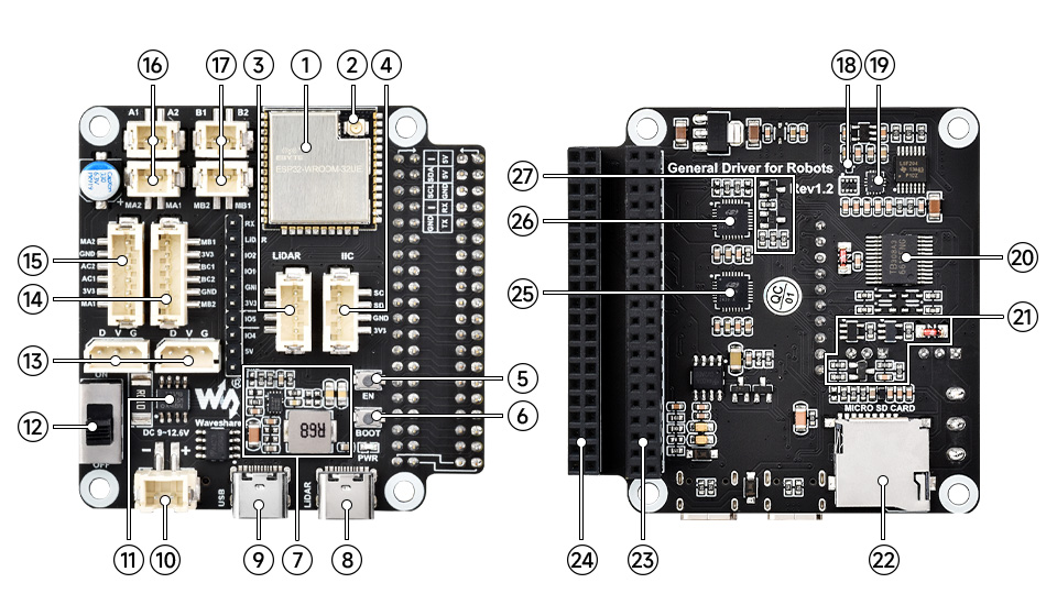 Image: Waveshare
Pin Assignments
Section titled “Pin Assignments”Both M2 and M3 firmware share the same GPIO mapping. The underlying hardware (the “General Driver for Robots” board) uses identical pin assignments — the difference is in how the H-bridge channels are used: the M2 drives external accessories (lights, solenoids) via the switch module, while the M3 drives mobile base motors.
| GPIO | Function | Notes |
|---|---|---|
| GPIO1 (TX) | Serial TX | Programming/debug UART |
| GPIO3 (RX) | Serial RX | Programming/debug UART |
| GPIO18 | Servo Serial RXD | Half-duplex servo bus (Serial1) |
| GPIO19 | Servo Serial TXD | Half-duplex servo bus (Serial1) |
| GPIO32 | I2C SDA | OLED, INA219, sensors |
| GPIO33 | I2C SCL | OLED, INA219, sensors |
| GPIO25 | H-bridge A PWM | M2: switch channel A / M3: motor A |
| GPIO26 | H-bridge B PWM | M2: switch channel B / M3: motor B |
| GPIO21 | H-bridge AIN1 | Direction control |
| GPIO17 | H-bridge AIN2 | Direction control |
| GPIO22 | H-bridge BIN1 | Direction control |
| GPIO23 | H-bridge BIN2 | Direction control |
| GPIO35 | Encoder A ch.A | Motor/wheel encoder (input only) |
| GPIO34 | Encoder A ch.B | Motor/wheel encoder (input only) |
| GPIO16 | Encoder B ch.B | Motor/wheel encoder |
| GPIO27 | Encoder B ch.A | Motor/wheel encoder |
Servo Bus
Section titled “Servo Bus”The arm uses serial bus servos connected on a daisy-chain bus. The “-S” models ship with ST3215 servos (plastic housing); the “-Pro” models use ST3235 servos (all-metal housing). Both share the same protocol, torque rating, and pinout — the metal construction provides better heat dissipation and more stable backlash over the servo’s lifetime.
M2 Servo Layout (5 servos)
Section titled “M2 Servo Layout (5 servos)”| Servo ID | Joint | Type |
|---|---|---|
| 11 | Base rotation | Single drive |
| 12 | Shoulder (driving) | Dual drive |
| 13 | Shoulder (driven) | Dual drive |
| 14 | Elbow | Single drive |
| 15 | Gripper / EoAT | Single drive |
M3 Servo Layout (7 servos)
Section titled “M3 Servo Layout (7 servos)”| Servo ID | Joint | Type |
|---|---|---|
| 11 | Base rotation | Single drive |
| 12 | Shoulder (driving) | Dual drive |
| 13 | Shoulder (driven) | Dual drive |
| 14 | Elbow | Single drive |
| 15 | Wrist pitch | Single drive |
| 16 | Wrist rotation | Single drive |
| 17 | Gripper | Single drive |
 The M3 wrist adds pitch (servo 15) and rotation (servo 16) between the elbow and gripper. Image: Waveshare
Servo Specifications
Section titled “Servo Specifications”| Parameter | ST3215 (“-S” models) | ST3235 (“-Pro” models) |
|---|---|---|
| Protocol | Half-duplex TTL serial | Half-duplex TTL serial |
| Baud rate | 1Mbps | 1Mbps |
| Torque | 30 kg.cm @ 12V | 30 kg.cm @ 12V |
| Speed | 40 rpm (no load) | 40 rpm (no load) |
| Resolution | 12-bit (4096 positions) | 12-bit (4096 positions) |
| Encoder | 12-bit magnetic (0.088°) | 12-bit magnetic (0.088°) |
| Housing | Plastic | All-metal |
| Feedback | Position, speed, load, voltage, temperature, current, mode | Position, speed, load, voltage, temperature, current, mode |
Electrical Specifications
Section titled “Electrical Specifications”| Parameter | Value |
|---|---|
| Input Voltage | 12V DC |
| Recommended PSU | 12V / 5A |
| Battery Support | 3S LiPo (11.1V nominal) |
| ESP32 Current | ~250mA typical |
| Servo Stall Current | ~1.5A per servo (peak) |
| Total Peak Current | ~6A (all servos stalling) |
| Switched Outputs | 12V, ±255 PWM, ~2A per channel |
| LED Max Current | ~20mA |
Mechanical Specifications
Section titled “Mechanical Specifications”| Parameter | M2-S | M2-Pro | M3-S | M3-Pro |
|---|---|---|---|---|
| Body Weight | 826g ± 15g | 873g ± 15g | 973.5g ± 15g | 1020.8g ± 15g |
| Clamp Weight | 290g ± 10g | 290g ± 10g | 290g ± 10g | 290g ± 10g |
| Horizontal Workspace | 1090mm | 1090mm | 1120mm | 1120mm |
| Vertical Reach | 798mm | 798mm | 798mm | 798mm |
| Repositioning Precision | ≈ ±4mm | ≈ ±4mm | ≈ ±5mm | ≈ ±5mm |
| Payload | 0.5kg @ 500mm | 0.5kg @ 500mm | 0.2kg @ 500mm | 0.2kg @ 500mm |
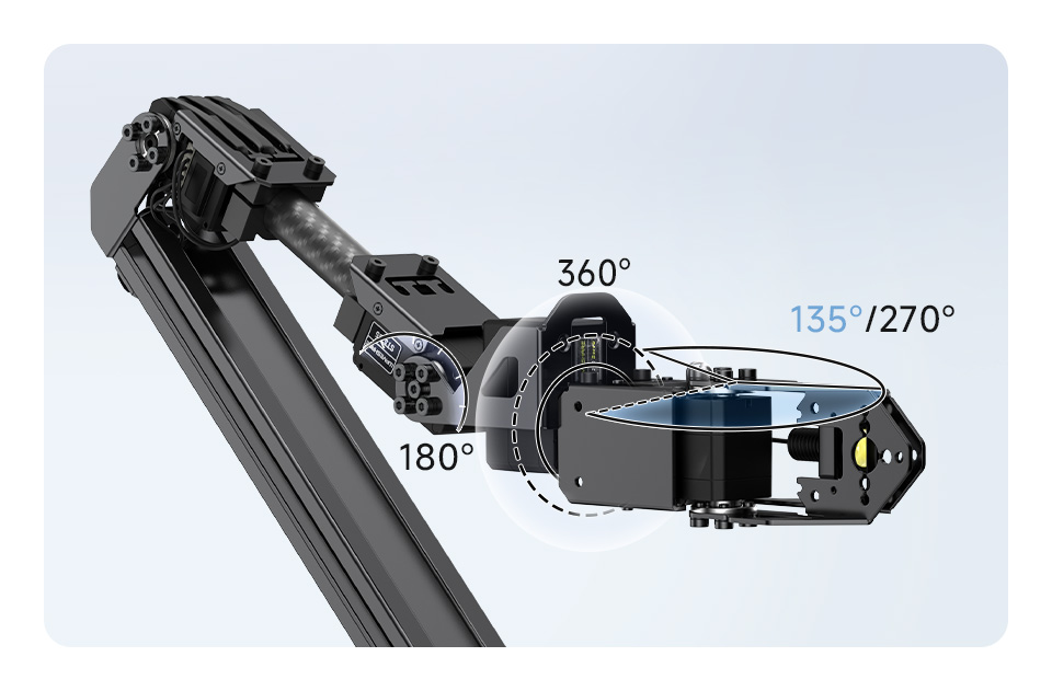
| Joint Ranges | Base 360°, Shoulder 180°, Elbow 180°, Hand 135°/270° | Same | Base 360°, Shoulder 180°, Elbow 225°, Wrist 180°+360°, Hand 180° | Same |
| Materials | Carbon fiber, 5052 aluminum | Carbon fiber, 5052 aluminum | Carbon fiber, 5052 aluminum | Carbon fiber, 5052 aluminum |
| Table Clamp | Supports edges up to 72mm | Supports edges up to 72mm | Supports edges up to 72mm | Supports edges up to 72mm |
Expansion Options
Section titled “Expansion Options”The driver board provides headers for:
- I2C bus — Connect sensors (IMU, distance, force), displays, or additional controllers
- SPI bus — High-speed peripherals
- 12V switched outputs — Solenoids, pumps, additional motors (controlled via
T:113) - Servo bus — Additional serial bus servos can be daisy-chained
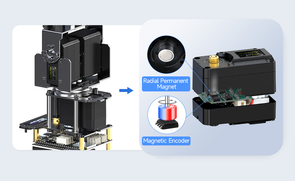 Image: Waveshare
The expansion plate on the arm’s forearm provides M3 mounting holes for custom end-effectors and sensors.
 Image: Waveshare
Hardware reference from the General Driver for Robots schematic, RoArm-M2-S Wiki, and RoArm-M3 Wiki. Images: Waveshare.